We think a little bit about Intel Skylake platform architecture. In recent years I have read many books and internet informations about outdated information about network cards and packet processing. Therefore I took a closer look at a modern Intel architecture. Furthermore it is interesting to see how Linux can be used with these new technologies (MSI-X, PCIe, DMA, multi queueing and some more.
More interesting articles:
- R80.x Architecture and Performance Tuning - Link Collection
- Article list (Heiko Ankenbrand)
PCI Express (Peripheral Component Interconnect Express), officially abbreviated as PCIe or PCI-e is a high-speed serial computer expansion bus standard, designed to replace the older PCI, PCI-X and AGP bus standards. PCIe has numerous improvements over the older standards, including higher maximum system bus throughput, lower I/O pin count and smaller physical footprint, better performance scaling for bus devices, a more detailed error detection and reporting mechanism (Advanced Error Reporting, AER), and native hot-swap functionality. More recent revisions of the PCIe standard provide hardware support for I/O virtualization.
Conceptually, the PCI Express bus is a high-speed serial replacement of the older PCI/PCI-X bus. One of the key differences between the PCI Express bus and the older PCI is the bus topology; PCI uses a shared parallel bus architecture, in which the PCI host and all devices share a common set of address, data and control lines. In contrast, PCI Express is based on point-to-point topology, with separate serial links connecting every device to the root complex (host).
In terms of bus protocol, PCI Express communication is encapsulated in packets. The work of packetizing and de-packetizing data and status-message traffic is handled by the transaction layer of the PCI Express port. At the software level, PCI Express preserves backward compatibility with PCI; legacy PCI system software can detect and configure newer PCI Express devices without explicit support for the PCI Express standard, though new PCI Express features are inaccessible.
The PCI Express link between two devices can consist of anywhere from one to 32 lanes. In a multi-lane link, the packet data is striped across lanes, and peak data throughput scales with the overall link width. The lane count is automatically negotiated during device initialization, and can be restricted by either endpoint. For example, a single-lane PCI Express (×1) card can be inserted into a multi-lane slot (×4, ×8, etc.), and the initialization cycle auto-negotiates the highest mutually supported lane count. The link can dynamically down-configure itself to use fewer lanes, providing a failure tolerance in case bad or unreliable lanes are present. The PCI Express standard defines slots and connectors for multiple widths: ×1, ×4, ×8, ×12, ×16 and ×32. This allows the PCI Express bus to serve both cost-sensitive applications where high throughput is not needed, as well as performance-critical applications such as networking (10 Gigabit Ethernet or multiport Gigabit Ethernet).
|
PCI Express
version
|
Line
code
|
Transfer
rate
|
Throughput
|
|
×1
|
×2
|
×4
|
×8
|
×16
|
|
3.0
|
128b/130b
|
8.0 GT/s
|
984.6 MB/s
|
1.97 GB/s
|
3.94 GB/s
|
7.88 GB/s
|
15.8 GB/s
|
| What is a hardware interrupt? |
When a data frame is written to RAM or core C1 cache via DMA, how does the NIC tell the rest of the system that data is ready to be processed?
Traditionally, a NIC would generate an interrupt request (IRQ) indicating data had arrived.
There are three common types of IRQs:
A device generating an IRQ when data has been written to RAM or core C1 cache via DMA is simple enough, but if large numbers of data frames arrive this can lead to a large number of IRQs being generated. The more IRQs that are generated, the less CPU time is available for higher level tasks like user processes.
In general, the interrupt handler which runs when an interrupt is raised should try to defer as much processing as possible to happen outside the interrupt context. This is crucial because while an interrupt is being processed, other interrupts may be blocked.
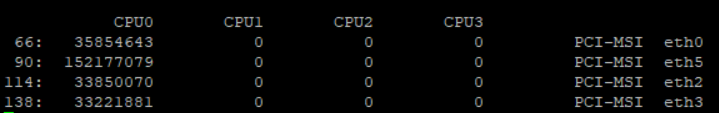
The following command shows the assignment of interrupts to network cards.
# cat /proc/interrupts

Message Signaled Interrupts (MSI) are an alternative in-band method of signaling an interrupt, using special in-band messages to replace traditional out-of-band assertion of dedicated interrupt lines. While more complex to implement in a device, message signaled interrupts have some significant advantages over pin-based out-of-band interrupt signaling.
Message signaled interrupts are supported in PCI bus since its version 2.2, and in later available PCI Express bus. Some non-PCI architectures also use message signaled interrupts.
Traditionally, a device has an interrupt line (pin) which it asserts when it wants to signal an interrupt to the host processing environment. This traditional form of interrupt signaling is an out-of-band form of control signaling since it uses a dedicated path to send such control information, separately from the main data path. MSI replaces those dedicated interrupt lines with in-band signaling, by exchanging special messages that indicate interrupts through the main data path. In particular, MSI allows the device to write a small amount of interrupt-describing data to a special memory-mapped I/O address, and the chipset then delivers the corresponding interrupt to a processor.
A common misconception with MSI is that it allows the device to send data to a processor as part of the interrupt. The data that is sent as part of the memory write transaction is used by the chipset to determine which interrupt to trigger on which processor; that data is not available for the device to communicate additional information to the interrupt handler.
As an example, PCI Express does not have separate interrupt pins at all; instead, it uses special in-band messages to allow pin assertion or deassertion to be emulated. Some non-PCI architectures also use MSI; as another example, HP GSC devices do not have interrupt pins and can generate interrupts only by writing directly to the processor's interrupt register in memory space. The HyperTransport protocol also supports MSI.
PCI defines two optional extensions to support Message Signaled Interrupts, MSI and MSI-X. While PCI Express is compatible with legacy interrupts on the software level, it requires MSI or MSI-X.
MSI - MSI (first defined in PCI 2.2) permits a device to allocate 1, 2, 4, 8, 16 or 32 interrupts. The device is programmed with an address to write to (generally a control register in an interrupt controller), and a 16-bit data word to identify it. The interrupt number is added to the data word to identify the interrupt. Some platforms such as Windows do not use all 32 interrupts but only use up to 16 interrupts.
MSI-X - MSI-X (first defined in PCI 3.0) permits a device to allocate up to 2048 interrupts. The single address used by original MSI was found to be restrictive for some architectures. In particular, it made it difficult to target individual interrupts to different processors, which is helpful in some high-speed networking applications. MSI-X allows a larger number of interrupts and gives each one a separate target address and data word. Devices with MSI-X do not necessarily support 2048 interrupts but at least 64 which is double the maximum MSI interrupts.
Optional features in MSI (64-bit addressing and interrupt masking) are also mandatory with MSI-X.
What is a software interupt?
|
The softirq system in the Linux kernel is a mechanism for executing code outside of the context of an interrupt handler implemented in a driver. This system is important because hardware interrupts may be disabled during all or part of the execution of an interrupt handler. The longer interrupts are disabled, the greater chance that events may be missed. So, it is important to defer any long running actions outside of the interrupt handler so that it can complete as quickly as possible and re-enable interrupts from the device.
There are other mechanisms that can be used for deferring work in the kernel, but for the purposes of the networking stack, we’ll be looking at softirqs.
The softirq system can be imagined as a series of kernel threads (one per CPU) that run handler functions which have been registered for different softirq events. If you’ve ever looked at top and seen ksoftirqd/0 in the list of kernel threads, you were looking at the softirq kernel thread running on CPU 0.
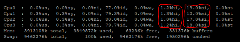
Software interrupts and hardware interrupts can be analyzed with "top" pro core.
# top

If your NIC supports multi queue or if you are attempting to optimize for data locality, you may wish to use a specific set of CPUs for handling interrupts generated by your NIC.
| The high level path a packet takes from arrival to SecureXL driver! |
At this point I see packet processing somewhat differently than described in many books. In my opinion there are some differences from the old Intel architecture with the ISA bus, which is still described in many books. From my point of view, no packets are copied from the network card into the memory, but directly into the core C1 cache. Also the interrupt processing takes place only after copying the packet into the core C1 cache. I'm not 100% sure that's the case here, though.
However, I am not one hundred percent sure that this is the case here either. Therefore we should clarify this with the R&D department if necessary.
According to my research, the Linux kernel should process the package as follows:
- Packet arrives at the NIC on the network wire
- The DMA hardware process copies the packet into the core C1 cache.
- A hardware interrupt (hi) via MSI or MSI-X is generated from NIC controller to let the Linux kernel know a packet is available in core C1 cache and therefore in the linux ring buffer.
- The NIC driver is called and an RX ring buffer slot with a descriptor referencing the new frame in core C1 cache receive buffer.
- At this point the Check Point software starts. The SecureXL driver processed packets off the ring buffert to depending on how many SecureXL (SND) instances are active, the packages are distributed to the corresponding SecureXL driver instance (New under R80.20 - SecureXL works in part in user mode).
- Now SecureXL and CoreXL process all packets vs. sessions. More information can be found in the following article:
https://community.checkpoint.com/docs/DOC-3041-r80x-security-gateway-architecture-logical-packet-flo...
| Intel Skylake arcitecture on HP Server DL360/380 G10 |
The Skylake platform will be divided between three major categories 2S, 4S and 8S. HP DL 360 G10 server use the S2 architecture. In the following example we will look at an HP DL 360 G10. I don't want to get into the depths of architecture here. We just want to look at the PCIe bus. This point is very interesting for the use of 10 GBit cards.
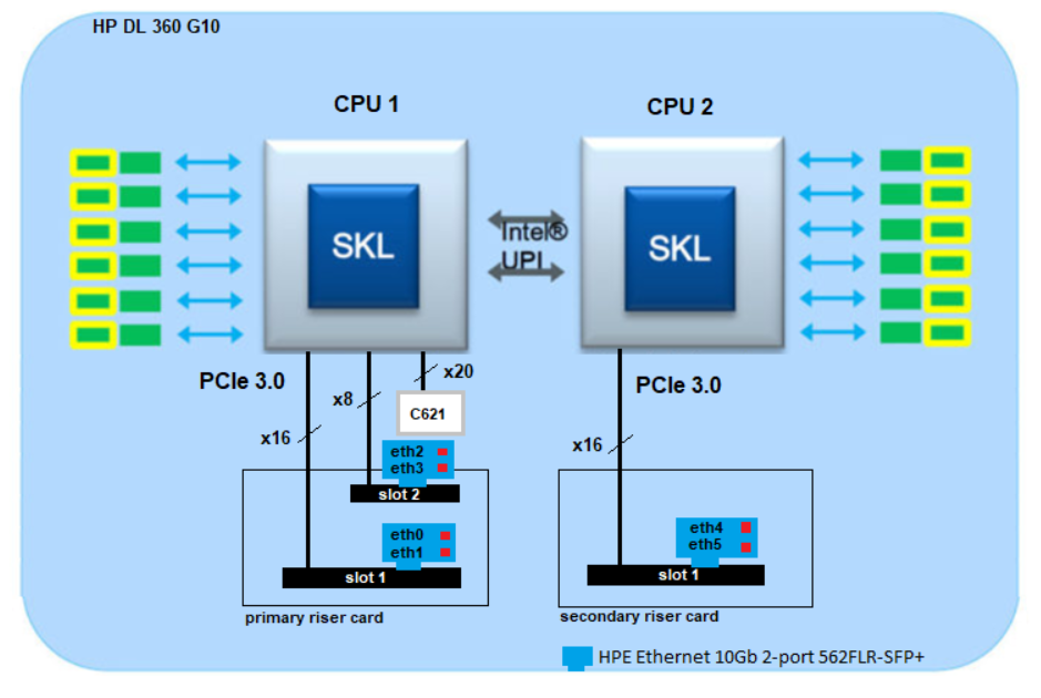
All Intel processors of the series Intel Xeon Platinum 8xxx, Gold 6xxx/5xxx, Silver 4xxx and Bronze 3xxx have a 48 lane PCIe 3.0 arcitetur. Another interesting point to note is the fact that not only will update the number of PCIe slots to 48 but they will finally be configurable in x4, x8 and x16 divisions.
The onboard interface on the server is provided by an Intel chip set C621. This chip set is connected to processor one (of two). It is also used for other devices like USB 3.0/2.0, SATA, 4x1GbE and others. The problem here is that 20 PCIe lane‘s are used for this C621 chipset. So in extreme cases only 28 (48-20) lanes remain for the riser card.
The riser cards are connected to different CPU‘s. With the DL 360 G10 this is as follows (see table).
|
Riser Card
|
Expantion Slot
|
Technology
|
Bus With
|
Prozessor
|
|
Primary
|
Slot 1
|
PCIe 3.0
|
x16
|
CPU1
|
|
|
Slot 2
|
PCIe 3.0
|
X8
|
CPU1
|
|
Secondary
|
Slot 1
|
PCIe 3.0
|
X16
|
CPU2
|
Here I see a small disadvantage with the construction of the HP servers. CPU one is responsible for the C621 chip set and provides a riser card for 2 slots (x16, x8) at the same time. Therefore only one slot with x8 remains, because all PCIe lanes are used (C621 = 20, slot 1=16 and slot 2=8). As discussed above, 48 lanes per CPU are possible. Thus slot two can no longer manage x16 PCIe cards (20+16+8=44 lanes). Therefore no x16 second slot for a network card is available. We could not currently use a network card in slot 2 that supports x16. But this is no problem either, since most 10 GB/s cards use x8 lanes.
What does that mean for the firewall on a open server HP DL360 G10?
The big question here was which architecture offers the higher throughput?
For this I have chosen three architectures:
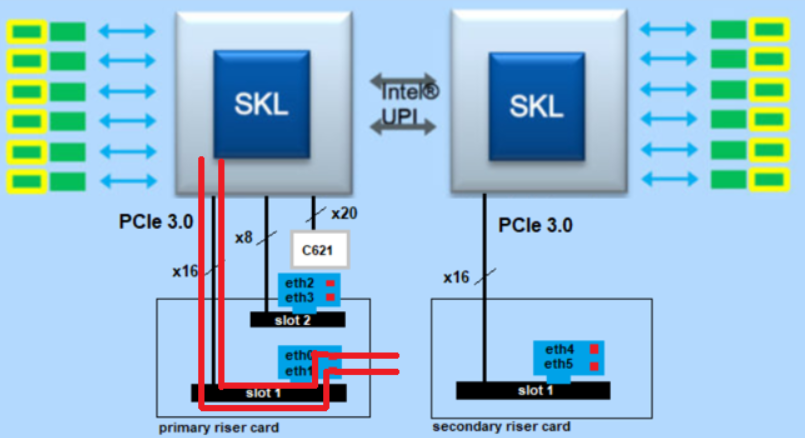
- Total traffic with one CPU from eth1 (primary riser card slot1) to eth2 (primary riser card slot2).
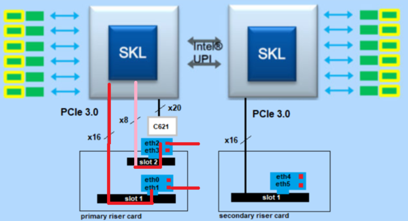

- Total traffic with one CPU from eth1 (primary riser card slot1) to eth0 (primary riser card slot1).

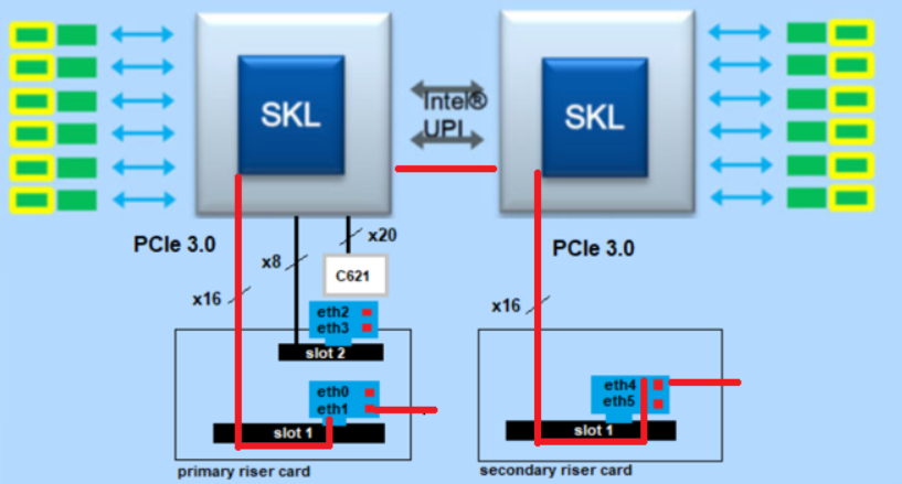
- The total traffic with two CPU's from eth1 (primary riser card slot1) to eth4 (secondary riser card slot2).

The big question is which architecture is faster?
Which problems can occur here with the Intel architecture?
Unfortunately I have no answer to these questions!
What is the prerequisite for using Multi Queue?
|
What is the prerequisite for using Multi Queue?
- Multi-Queue applies only if SecureXL is enabled.
- Multi-Queue is not supported on computers with one CPU core.
- Network interfaces must use the driver that supports Multi-Queue. Only network cards that use the igb (1Gb), ixgbe (10Gb), i40e (40Gb), or mlx5_core (40Gb) drivers support the Multi-Queue.
- You can configure a maximum of five interfaces with Multi-Queue.
- You must reboot the Security Gateway after all changes in the Multi-Queue configuration.
- For best performance, it is not recommended to assign both SND and a CoreXL FW instance to the same CPU core.
- Do not change the IRQ affinity of queues manually. Changing the IRQ affinity of the queues manually can adversely affect performance.
- Multi-Queue is relevant only if SecureXL and CoreXL is enabled.
- Do not change the IRQ affinity of queues manually. Changing the IRQ affinity of the queues manually can adversely affect performance.
- You cannot use the “sim affinity” or the “fw ctl affinity” commands to change and query the IRQ affinity of the Multi-Queue interfaces.
- The number of queues is limited by the number of CPU cores and the type of interface driver:
|
Network card driver
|
Speed
|
Maximal number of RX queues
|
|
igb
|
1 Gb
|
4
|
|
ixgbe
|
10 Gb
|
16
|
|
i40e
|
40 Gb
|
14
|
|
mlx5_core
|
40 Gb
|
10
|
More informations here:
https://community.checkpoint.com/docs/DOC-3352-r80x-performance-tuning-tip-multi-queue
➜ CCSM Elite, CCME, CCTE, CCVS ➜ www.checkpoint.tips